1. Stress Analysis of a Cantilever Beam 🗽️
Objective: Simulate and analyze the stress distribution on a cantilever beam under different loads using ANSYS.
Introduction
Cantilever beams are fundamental elements in engineering structures, used in everything from bridges to airplane wings. Understanding how forces act on them is critical for engineers. Stress analysis using ANSYS provides a clear visualization of how the beam behaves under load, making it an ideal project for students starting with finite element analysis (FEA).
$$\sigma = \frac{M \cdot y}{I}$$
Project Overview
The goal is to model a cantilever beam in ANSYS and analyze its stress distribution. Students will learn to set up a problem, apply boundary conditions, and interpret results. By experimenting with different materials and loads, you can explore real-world applications of stress analysis.

Steps to Execute
- Beam Design in ANSYS:
- Open ANSYS Workbench and drag the "Static Structural" module into the project workspace.
- Use the DesignModeler to create a simple rectangular cantilever beam. For instance, define the dimensions as:
- Length: 1 meter
- Width: 0.1 meter
- Height: 0.1 meter
- Material Selection:
- Assign material properties like steel or aluminum from the ANSYS material library.
- Ensure the Young's modulus and Poisson's ratio are specified correctly.
- Boundary Conditions:
- Fix one end of the beam completely (to simulate a cantilever).
- Apply a point load or distributed load at the free end.
- Meshing:
- Generate a finite element mesh for the beam. Use a finer mesh for more accurate results.
- Perform a mesh refinement study to ensure convergence of results.
- Simulation and Results:
- Solve the simulation.
- Visualize the stress distribution using ANSYS’ post-processing tools.
- Key results include maximum von Mises stress, displacement, and deformation.
Key Insights
- Stress Distribution: Observe how stress increases near the fixed end and decreases towards the free end.
- Material Behavior: Analyze how different materials (e.g., steel vs. aluminum) respond to the same load.
- Load Variations: Compare the impact of varying load magnitudes and types (point vs. distributed).
Challenges and Learning Outcomes
- Challenges: Understanding meshing intricacies and interpreting stress contours can be tricky initially. However, practice with different models will help.
- Learning Outcomes:
- Gain a strong grasp of FEA principles.
- Learn to use ANSYS Mechanical for structural simulations.
- Develop insights into real-world engineering problems.
Real-World Applications
- Bridges: Cantilever beams are widely used in bridge construction.
- Aircraft Wings: Understanding cantilever principles is crucial for aerospace engineering.
- Robotics: Analyze robotic arms or similar structures.
By completing this project, students will build a solid foundation in stress analysis, readying them for more complex simulations and industry scenarios.
2. Thermal Analysis of a Heat Sink ❄️🔥
Objective: Optimize the heat dissipation capabilities of a heat sink used in electronic devices through thermal analysis in ANSYS.
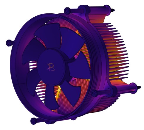
Introduction
In modern electronics, managing heat is vital to prevent component failure. Heat sinks, designed to dissipate heat efficiently, are critical in devices like CPUs and GPUs. This project uses ANSYS to study the thermal performance of a heat sink, providing practical insights into thermal management.
Project Overview
The project involves creating a heat sink model, applying thermal loads, and simulating heat dissipation. By experimenting with different geometries and materials, students can learn how design affects thermal efficiency.
Steps to Execute
- Heat Sink Design:
- Use ANSYS DesignModeler to create a simple heat sink model with fins.
- Example dimensions:
- Baseplate: 100 mm x 100 mm
- Fins: Height 50 mm, Thickness 2 mm, Spacing 5 mm
- Material Assignment:
- Assign materials like aluminum or copper (commonly used for heat sinks).
- Specify thermal conductivity values.
- Boundary Conditions:
- Apply a heat source to the baseplate (e.g., 50 W power input).
- Define convective cooling on the fin surfaces (simulate airflow with a heat transfer coefficient, e.g., 25 W/m²K).
- Meshing:
- Use a fine mesh near the fins to capture temperature gradients accurately.
- Simulation and Results:
- Run a steady-state thermal simulation.
- Examine the temperature distribution and heat flux.
- Optimize the design by tweaking fin geometry and spacing.
Key Insights
- Temperature Distribution: Observe how heat spreads through the heat sink and dissipates into the surroundings.
- Material Efficiency: Compare the performance of aluminum vs. copper.
- Geometry Optimization: Analyze the impact of fin size, number, and spacing on thermal performance.
Challenges and Learning Outcomes
- Challenges: Setting realistic boundary conditions and achieving mesh convergence can be tricky.
- Learning Outcomes:
- Understand the principles of heat transfer and thermal conductivity.
- Learn to optimize designs for thermal efficiency.
- Master the use of ANSYS for thermal simulations.
Real-World Applications
- Electronics: Design heat sinks for CPUs, GPUs, or power transistors.
- Automotive: Analyze cooling systems for electric vehicle batteries.
- Industrial: Improve heat exchangers in HVAC systems.
By completing this project, students gain critical skills in thermal analysis, preparing them for careers in electronics, automotive, and energy industries.
3. CFD Simulation of Airflow Over an Airfoil ✈️
Objective: Simulate and analyze the airflow over an airfoil to understand lift, drag, and flow characteristics using ANSYS Fluent.

Introduction
Aerodynamic efficiency is crucial in industries like aerospace and automotive. Airfoil analysis helps engineers design structures with minimal drag and maximum lift. This project focuses on using computational fluid dynamics (CFD) in ANSYS Fluent to study airflow patterns and forces acting on an airfoil.
$$C_L = \frac{L}{0.5 \cdot \rho \cdot v^2 \cdot A}$$
Project Overview
Students will design an airfoil, simulate airflow at various angles of attack, and analyze parameters such as lift coefficient, drag coefficient, and pressure distribution. This project introduces the basics of fluid dynamics simulation and its application in engineering.
Steps to Execute
- Airfoil Design:
- Import a standard airfoil shape (e.g., NACA 0012) or create your own using coordinates.
- Use ANSYS DesignModeler to define the airfoil geometry and surrounding fluid domain.
- Meshing:
- Generate a structured mesh around the airfoil, ensuring finer elements near the surface to capture boundary layer effects.
- Perform a mesh independence study to validate results.
- Boundary Conditions:
- Set inlet velocity to simulate wind speed (e.g., 50 m/s).
- Define outlet pressure and apply no-slip conditions on the airfoil surface.
- Adjust the angle of attack to observe different airflow patterns.
- Simulation Setup:
- Use ANSYS Fluent to solve the problem using a turbulence model (e.g., k-ε or k-ω).
- Run steady-state or transient simulations based on project scope.
- Results and Analysis:
- Visualize pressure and velocity contours.
- Calculate lift and drag forces and compare them for different angles of attack.
- Study flow separation and vortex formation at high angles of attack.
Key Insights
- Flow Characteristics: Understand how airflow interacts with the airfoil surface.
- Lift and Drag: Learn how design changes affect aerodynamic performance.
- Optimization: Explore ways to improve airfoil efficiency by altering geometry.
Challenges and Learning Outcomes
- Challenges: Achieving mesh independence and interpreting turbulent flow behavior can be challenging.
- Learning Outcomes:
- Master the basics of CFD simulations.
- Develop an understanding of aerodynamic principles.
- Learn to optimize designs for reduced drag and increased lift.
Real-World Applications
- Aerospace: Design efficient wings and propellers.
- Automotive: Improve the aerodynamics of vehicles.
- Renewable Energy: Analyze wind turbine blade performance.
By completing this project, students gain practical CFD skills and insights into aerodynamic optimization.
4. Modal Analysis of a Bridge Structure 🌋
Objective: Perform modal analysis of a bridge structure to study its natural frequencies and vibration modes using ANSYS.

Introduction
Understanding the vibrational behavior of structures is crucial to ensuring their safety and performance. Modal analysis identifies natural frequencies and mode shapes, helping engineers design bridges that can withstand dynamic forces like wind and traffic.
$$f = \frac{1}{2\pi} \sqrt{\frac{k}{m}}$$
Project Overview
This project involves creating a simplified bridge model, performing modal analysis, and interpreting the vibration modes. It’s an excellent way for students to learn about structural dynamics and resonance.
Steps to Execute
- Bridge Model Creation:
- Use ANSYS DesignModeler to create a basic bridge geometry (e.g., a beam or truss structure).
- Define realistic dimensions and material properties.
- Meshing:
- Generate a mesh with appropriate element sizes for accuracy.
- Ensure mesh refinement at critical points like joints or supports.
- Boundary Conditions:
- Apply fixed supports at the ends or supports of the bridge.
- Ensure no external loads are applied (as modal analysis is load-independent).
- Simulation Setup:
- Use the Modal Analysis module in ANSYS.
- Define the number of modes to extract (e.g., first six natural frequencies).
- Results and Analysis:
- Observe mode shapes and frequencies.
- Identify critical modes where resonance might occur.
- Compare results for different materials or structural designs.
Key Insights
- Natural Frequencies: Understand how material and geometry affect vibration.
- Mode Shapes: Visualize how the structure deforms under each mode.
- Dynamic Behavior: Analyze the impact of resonance on structural stability.
Challenges and Learning Outcomes
- Challenges: Interpreting mode shapes and ensuring correct boundary conditions can be tricky.
- Learning Outcomes:
- Learn to perform dynamic simulations in ANSYS.
- Understand the importance of avoiding resonance in design.
- Develop insights into structural dynamics.
Real-World Applications
- Civil Engineering: Design safer bridges and buildings.
- Mechanical Engineering: Analyze machine components for vibrational stability.
- Aerospace: Study the dynamic behavior of aircraft structures.
This project equips students with foundational knowledge of modal analysis, an essential skill for structural engineers.
5. Fluid-Structure Interaction in a Pipe System ⚡
Objective: Study the interaction between fluid flow and structural deformation in a pipe system using ANSYS.

Introduction
Fluid-Structure Interaction (FSI) is a multidisciplinary field that analyzes how fluids affect structural behavior and vice versa. This project explores FSI in a pipe system, focusing on pressure-induced deformation and flow changes.
$$\Delta P = \rho \cdot g \cdot h$$
Project Overview
Students will simulate a fluid flow through a pipe and analyze how the structure deforms under pressure. This project introduces coupled field analysis and its applications in industries like oil and gas.
Steps to Execute
- Pipe System Design:
- Create a pipe geometry in ANSYS DesignModeler.
- Define inlet and outlet sections and include bends or junctions for complexity.
- Material Properties:
- Assign materials to the pipe (e.g., steel) and fluid (e.g., water).
- Specify elastic modulus for the structure and density/viscosity for the fluid.
- Boundary Conditions:
- Apply inlet pressure or velocity for the fluid.
- Define outlet conditions (e.g., zero pressure).
- Fix the pipe ends to simulate realistic constraints.
- FSI Simulation Setup:
- Use ANSYS Fluent for fluid flow simulation and ANSYS Mechanical for structural analysis.
- Couple the simulations to analyze interactions.
- Results and Analysis:
- Visualize pressure and velocity fields within the fluid.
- Observe structural deformation and stress distribution.
- Analyze feedback loops where deformation affects flow.
Key Insights
- Pressure-Induced Deformation: Understand how internal pressure affects pipe integrity.
- Coupled Behavior: Study the bidirectional interaction between fluid flow and structure.
- Optimization: Explore design changes to reduce stress or improve flow efficiency.
Challenges and Learning Outcomes
- Challenges: Setting up coupled simulations and ensuring convergence can be complex.
- Learning Outcomes:
- Master coupled field simulations.
- Learn to optimize designs for FSI.
- Develop insights into multidisciplinary engineering problems.
Real-World Applications
- Oil and Gas: Design pipelines to withstand high pressures.
- Aerospace: Analyze fuel systems and hydraulic lines.
- Biomedical: Study blood flow in arteries and veins.
By completing this project, students gain expertise in FSI, preparing them for careers in industries that require multidisciplinary analysis.
Need suggestions? let's talk here.
Check out YouTube channel, published research
you can contact us (bkacademy.in@gmail.com)
Interested to Learn Engineering modelling Check our Courses 🙂
All product names, trademarks, and registered trademarks mentioned in this article are the property of their respective owners. Use of these names does not imply any affiliation, endorsement, or sponsorship. The views expressed are those of the author and do not necessarily represent the views of any organizations with which they may be affiliated. This content is provided for educational and informational purposes only and should NOT be construed as official guidance.
