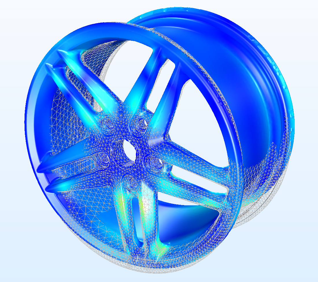
The finite element method (FEM) is a popular technique for numerically solving differential equations in engineering and mathematics. Finite Element Method simulation in COMSOL is a well-known simulation workflow. The classic domains of structural analysis, heat transfer, fluid flow, mass transport, and electromagnetic potential are typical issue areas of interest.
In two or three spatial variables, the FEM is a generic numerical approach for solving partial differential equations (i.e., some boundary value problems). The FEM breaks a big system into smaller, simpler sections called finite elements in order to solve a problem. This is accomplished by a specific space discretization in the spatial dimensions, which is accomplished through the creation of a mesh of the object: the numerical domain for the solution, which has a finite number of points.
A system of algebraic equations emerges from the finite element technique description of a boundary value issue. Over the domain, the approach approximates the unknown function. These basic equations are then combined into a bigger system of equations that models the full situation. The FEM then uses the calculus of variations to approximate a solution by minimising an associated error function.

What Are the Benefits of Using Finite Element Analysis Application?
When creating, optimising, or regulating a device or process, finite element analysis (FEA) software is used to decrease the number of prototypes and trials that must be done. This does not necessarily imply that using FEA saves money for businesses and research organisations. They do, however, receive more development for their money, which might give them an advantage over the competitors. As a result, it may be appropriate to raise FEA's research and development budget.
Geometry in FEM
The model geometry must be "watertight" when using finite element analysis. Geometries from computer-aided design (CAD) aren't usually employed for analysis. This means that anything that is a volume in the actual world may be expressed in a CAD design by a collection of loosely linked 3D surfaces. These surfaces must really constitute a genuine volume in finite element analysis.
Even though a group of 3D surfaces in a CAD design constitute a volume, certain surfaces may be too thin and some edges may be too short in comparison to the geometry's size. As a consequence, there is an unfavourable concentration of components at the problematic geometrical characteristics.
Repairing and defeaturing of CAD geometry is often necessary in order to prepare it for finite element analysis. Repairing fixes the elements of the geometry that aren't "watertight," but defeaturing may eliminate thin surfaces or combine tiny edges that aren't essential.
Mesh in Finite Element Method simulation in COMSOL
Interested to Learn Engineering modelling? Check our Courses?
Without discretization, geometry, materials, domain settings, boundary conditions, starting conditions, loads, and restrictions may be defined. This is still done for the discretized model in many older FEA tools. Once the mesh is constructed, the numerical model is complete. Various occurrences and analysis need different mesh settings. To address wave propagation issues, such as modelling elastic waves in structural mechanics or electromagnetic waves in radio frequency analysis, the biggest element must be much smaller than the wavelength.
Boundary layer meshes may be needed to resolve boundary layers in fluid flow, while the cell Reynolds number may define the element size in the bulk of the fluid. In classical FEA, meshing is regarded as one of the most complex preprocessing operations. A starting mesh in current FEA software may be automatically changed throughout the solution process to minimise or eliminate numerical solution error. Adaptive meshing is the term for this.
For help in modelling in any FEA, FDTD, DFT Simulation / Modelling work, you can contact us (bkcademy.in@gmail.com) or in any platform.
Interested to Learn Engineering modelling? Check our Courses?
u can follow us on social media
Share the resource
-.-.-.-.-.-.-.-.-.().-.-.-.-.-.-.-.-.-
© bkacademy
