Introduction
Mesh generation stands as a foundational step in the finite element analysis (FEA) workflow, especially within the COMSOL Multiphysics environment. In essence, meshing discretizes the simulation domain into smaller, finite subregions—termed elements—where the governing equations can be numerically approximated. Despite being preparatory, this step has far-reaching implications for the accuracy, efficiency, and reliability of simulation results.
In contemporary computational science and engineering, the sophistication of multiphysics models has surged. These models now regularly span coupled domains such as thermal-structural interaction, fluid-structure coupling, and electromagnetic-thermal systems. The inherent complexity demands meshing strategies that are not only robust and intelligent but also customizable to nuanced geometries and boundary conditions. An inaccurate or poorly constructed mesh may compromise convergence, inflate computational cost, or produce fundamentally flawed outputs.
To guide professionals navigating these challenges, COMSOL provides a wealth of resources like the Mesh Guides for COMSOL Multiphysics and its continuously updated official documentation. These references underline the importance of meshing as not just a pre-processing task but as an artform and science critical to simulation success.
Finite Element Mesh Essentials
Understanding meshing within COMSOL begins with the finite element method (FEM) itself. FEM divides a domain into discrete parts, known as elements, where the solution is interpolated using basis functions. The fidelity of this interpolation—and consequently the accuracy of the entire simulation—depends heavily on the mesh's quality.

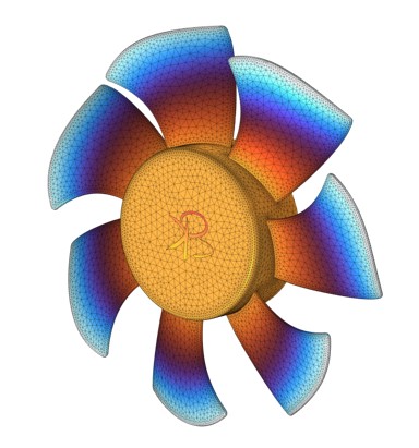
COMSOL supports a variety of mesh element types, including tetrahedra, hexahedra, prisms, pyramids, and their 2D counterparts. Each has its situational advantage. For instance, tetrahedra excel in general-purpose 3D meshing, while hexahedra are favored in structured, rectangular domains for their numerical efficiency.

COMSOL provides two main meshing approaches: physics-controlled and user-controlled. Physics-controlled meshing is ideal for rapid setup and preliminary simulations. It adapts the mesh density based on the underlying physics, providing a balance between detail and efficiency. In contrast, user-controlled meshing offers fine-tuned control over element size, growth rate, curvature resolution, and boundary refinement. This method is indispensable when tackling complex geometries, sharp interfaces, or localized phenomena that demand targeted mesh refinement.
Quantifying mesh quality involves metrics such as aspect ratio, skewness, and element growth rate. For instance, elements with high aspect ratios can degrade solution quality, particularly in regions of rapid gradient variation. Another recurring issue arises from geometrical artifacts—small edges, narrow slivers, and sharp vertices—which can destabilize the meshing algorithm or lead to excessively dense regions.
The COMSOL Learning Center offers excellent tutorials, including guidance on using swept meshes for axisymmetric or extruded geometries. Another crucial technique is sequential meshing, discussed in this article, which allows for iterative refinement based on solver feedback, ensuring that the mesh adapts dynamically to the model's evolving requirements.
For readers actively working in photonics, MEMS, or electromagnetics domains where subwavelength or nanoscale features prevail mesh quality becomes even more critical. If you need support with FEA simulation, model setup, or tricky boundary conditions, feel free to contact me.
Top 5 Approaches for Accurate Meshing in COMSOL
Effective meshing in COMSOL is not a one-size-fits-all endeavor. Depending on the physical domain, geometry complexity, and computational resources, different meshing strategies may be more appropriate. Here, we examine five powerful approaches that stand out in achieving accuracy, stability, and efficiency across diverse simulation scenarios.
Physics-Controlled Meshing
COMSOL’s physics-controlled meshing is a go-to starting point for many simulations. This automated approach adapts element sizing and distribution based on both geometry and physics interfaces. For instance, in an electromagnetics simulation, the meshing algorithm tightens the element size near high-gradient zones like waveguide bends or dielectric transitions. This ensures that the mesh conforms to the skin depth or wavelength-specific requirements of the problem.
While this method saves time and simplifies setup, it is not without limitations. For complex assemblies or when dealing with features at multiple scales, the user may find the physics-controlled mesh overly conservative or insufficiently detailed in critical regions. Still, as outlined in the COMSOL resource on efficient meshing, this strategy remains invaluable for preliminary studies and parameter sweeps.
Few important videos related to mesh:
| Title | Watch Link |
|---|---|
| Mesh Concepts and Tips in COMSOL Multiphysics | Watch |
| Mesh tips for Advanced Simulations in COMSOL | Watch |
| Mesh tips and tricks combined full video | Watch |
| User controlled Mesh for Complex Geometries - Manual mesh | Watch |
| Learn to Fix 🔍 Meshing error and Geometry technique in COMSOL | Watch |
User-Controlled Meshing
When precision matters or when dealing with highly intricate domains, user-controlled meshing is indispensable. This approach allows the analyst to explicitly define meshing sequences, control element types, and enforce custom sizing. One can even script mesh operations to iterate over different resolutions or adapt to solver feedback.
For example, in microfluidics models where channel height differences span several orders of magnitude, user-defined boundary layer mesh parameters can capture the near-wall velocity gradients more effectively than the automatic routines. Similarly, in semiconductor modeling, localized refinement near junctions or depletion regions benefits from manual intervention.
Resources such as the Mesh Guides for COMSOL offer deep dives into setting up customized mesh sequences.
Swept Meshing
Swept meshes are especially effective in domains with an extruded or axisymmetric structure. These meshes use structured elements (typically hexahedra) along the extrusion direction, yielding better convergence and lower element count compared to unstructured tetrahedral meshes.
A classic application is in pipe flow simulations or heat exchangers, where the geometry is predominantly linear or cylindrical. Swept meshing ensures that numerical diffusion is minimized and that the solver benefits from consistent element alignment.
COMSOL’s tutorial on swept meshes demonstrates how to set up such meshes using source and target boundaries, and how to address common pitfalls like element collapse or inversion.
Boundary Layer Meshing
Capturing steep gradients near surfaces—such as thermal boundary layers or velocity profiles in turbulent flows—demands specialized boundary layer meshing. These meshes stack thin prismatic elements adjacent to walls, ensuring adequate resolution without inflating the overall mesh size.
This approach is crucial in CFD and heat transfer problems, particularly those involving high Reynolds numbers or intricate wall interactions. COMSOL 6.0 has notably improved this feature with more adaptive growth rates and curvature detection, as shown in the COMSOL 6.0 Release Highlights.
Mesh Import and Unification
In advanced workflows that involve CAD integration or anatomical modeling, imported meshes must often be unified with native COMSOL geometries. The union operation introduced in recent COMSOL versions facilitates this process, merging different mesh parts into a coherent simulation domain.
This is particularly relevant in biomedical simulations or structural mechanics, where data from CT scans or external software like SolidWorks is converted into a usable mesh. With COMSOL's enhanced capability to detect and smooth inconsistencies at mesh interfaces, simulations now run more robustly even with heterogeneous mesh origins.
For detailed insights into mesh updates, the release notes provide a comprehensive overview.
Recent Developments
The meshing capabilities in COMSOL have matured significantly with recent updates, particularly with the release of version 6.0. These enhancements are not merely incremental—they address long-standing limitations and introduce features that expand what users can achieve in both academic and industrial simulations.
One of the most notable advancements is the inclusion of curved elements. Traditional linear elements can introduce geometric discretization errors, particularly in high-frequency electromagnetic or structural eigenfrequency simulations. Curved elements help resolve this by more faithfully conforming to the original geometry. This is especially critical when modeling structures with circular arcs or ellipses, such as antennas or turbine blades, where accuracy depends heavily on boundary fidelity. The inclusion of these elements ensures smoother field representations and better convergence with fewer mesh refinements.
COMSOL 6.0 has also refined its boundary layer meshing by improving the growth factor control and edge smoothing algorithms. As discussed in the release update, these upgrades allow users to better capture steep gradients without manual tuning, streamlining the simulation setup process.
Another substantial improvement is the new Union operation, which merges intersecting or adjacent imported meshes into a single unified entity. This feature is particularly useful for integrating third-party geometry or anatomical models from external meshing software. For example, a biomedical researcher may import a heart mesh from a DICOM file and unify it with a stent model built in COMSOL, allowing multiphysics analysis on the complete structure. The process not only simplifies geometry handling but also ensures numerical continuity across interfaces.
Automatic detection and removal of small geometric features is another helpful addition. Tiny slivers or narrow gaps often plague CAD imports, leading to meshing failures or excessively fine elements. The updated mesh module intelligently identifies such artifacts and either eliminates or simplifies them, reducing preprocessing time and enhancing solver stability.
The COMSOL webinar on meshing provides a visual walkthrough of these new features in action and offers real-world examples of how they can be leveraged to improve simulation workflows.
Challenges and Open Questions in Meshing
Despite advances in meshing algorithms and automation, several persistent challenges continue to confront simulation professionals using COMSOL. These issues often demand both technical intuition and experience, especially when working with multiphysics models or intricate geometries.
One of the most fundamental dilemmas is balancing mesh density against computational cost. A finer mesh generally increases accuracy but can exponentially escalate memory usage and simulation time. Determining “how fine is fine enough” remains an open question in many domains. This balance is especially precarious in time-dependent or nonlinear simulations, where solver performance can degrade dramatically with over-meshing.
Handling complex geometries introduces another layer of difficulty. CAD models imported from external sources often contain intricate details such as fillets, tiny holes, or sharp intersections. While these features may be negligible to the underlying physics, they can severely impair meshing operations. Sliver elements or tiny faces can cause mesh failure or necessitate unreasonably small global element sizes. COMSOL's feature detection tools and virtual operations offer partial relief, but expert judgment is often necessary to simplify geometry intelligently without compromising the model’s physical integrity.
Ensuring mesh independence and solution convergence remains a cornerstone of credible simulation practice. Ideally, one should perform a mesh convergence study—where simulation results are compared across increasingly finer meshes until the output stabilizes. However, such studies are often skipped due to time constraints or misunderstood as optional. In multiphysics simulations involving thermal stress or electromagnetic-fluid interactions, convergence behavior can vary between domains, further complicating validation.
Automatic meshing, while powerful, has limits—particularly with highly irregular domains or when integrating imported mesh files. Despite COMSOL’s improvements, it may still misinterpret complex edge connectivity or apply suboptimal mesh density. This can result in convergence warnings, nonphysical results, or excessive simulation times.
The broader meshing community remains divided on best practices for mesh refinement and validation. Forums such as Reddit highlight this diversity of opinion, showcasing workflows that range from fully manual refinement to reliance on adaptive solvers. For instance, some engineers swear by tetrahedral meshing with local refinement, while others favor hex-dominant strategies for mechanical simulations.
If you're navigating similar challenges—especially with boundary conditions, complex material models, or coupled physics—don’t hesitate to contact me. I regularly help researchers troubleshoot mesh and solver issues across optics, thermodynamics, and mechanics.
Opportunities and Future Directions
As simulation demands become more multidisciplinary and computationally intensive, the future of meshing in COMSOL—and in the broader finite element ecosystem—is poised for transformative change. Emerging technologies and evolving user needs are reshaping expectations around what mesh generation should be: intelligent, integrated, and iterative.
One of the most exciting prospects is the integration of AI-driven mesh optimization. These systems promise to learn from past simulations, adapting mesh density and element distribution in real time based on physics complexity and solver feedback. While still in its early stages, such adaptive meshing could substantially reduce preprocessing time and help users automatically balance accuracy with computational efficiency. Companies like Quanscient are already exploring such hybrid approaches to simulation workflows.
Improved interoperability with third-party CAD and meshing tools is another area of active development. Engineers and designers increasingly rely on software ecosystems that span multiple platforms—from SolidWorks to Rhino to Ansys. Enhancing the ability to import, unify, and mesh such geometries without data loss or topology errors will be critical in making COMSOL more versatile in design-to-simulation pipelines.
Real-time mesh quality feedback is a highly desired feature on the horizon. Currently, users often detect poor mesh elements only during the solver stage, when nonlinearities or convergence issues emerge. A system that flags high aspect ratios, skewed elements, or disconnected nodes during mesh generation would significantly improve productivity and model stability.
Another trend is the rise of cloud-based simulation platforms. These offer not just computational scalability but also collaborative mesh and model setup environments. Imagine multiple researchers working on different regions of a mesh or reviewing element quality metrics in real-time—this is increasingly feasible with cloud-native COMSOL applications and high-performance computing (HPC) integrations. Such platforms could revolutionize how simulations are designed and shared, particularly in academic labs or cross-disciplinary industry teams.
The vision of seamless meshing also extends to automated error estimation. Future tools may analyze simulation results dynamically and suggest targeted mesh refinement zones, not unlike adaptive remeshing used in computational fluid dynamics. This approach is especially relevant for simulations with localized stress concentrations or thermal hotspots.
As the modeling community continues to push boundaries—from nanophotonics to structural health monitoring—these developments will be critical to keeping simulation workflows robust and scalable.
Real-World Use Cases
The theoretical principles of meshing become most impactful when grounded in real-world applications. Across various disciplines, engineers and researchers have leveraged COMSOL's meshing capabilities to solve complex, high-stakes problems with greater efficiency and accuracy. Below are a few exemplary cases that highlight the practical value of intelligent meshing strategies.
Shape Optimization in Structural Engineering
In civil and mechanical engineering, the design of beams, trusses, and load-bearing structures often involves iterative shape optimization. One study employed refined meshing in stress concentration zones to optimize the geometry of a cantilever beam under torsion and bending loads. By increasing mesh density near the support and load application points, researchers achieved more accurate stress distribution predictions, leading to a 12% reduction in material usage without compromising safety. Detailed workflows for such simulations can be found in the Mesh Guides for COMSOL, which outline how to pair mesh refinement with parametric sweeps and optimization modules.
Thermal Management in Electronics
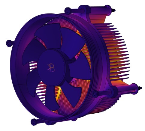
Miniaturization in electronics has made thermal simulation more critical than ever. In a case involving a compact power amplifier, boundary layer meshing was used to accurately resolve the steep temperature gradients near the device casing and heat sink. Standard meshing failed to capture the micro-level heat spreading, resulting in an underprediction of junction temperature by over 20°C. By implementing thin-layer prism meshes around the high-flux regions, the updated model aligned much more closely with experimental thermography results. These techniques are well-documented in the COMSOL 6.0 release, which details improvements in thermal meshing accuracy.
Biomedical Device Simulation
Patient-specific modeling in the biomedical field exemplifies the power of mesh import and unification. One research group simulated blood flow through a stented artery by importing a mesh generated from a CT scan and integrating it with a CAD model of a stent. The resulting simulation accounted for the interaction between blood flow and the stent geometry, offering predictive insights into areas prone to clot formation. This integration was facilitated by COMSOL’s new union operation and smoothing tools, as shown in the meshing webinar, which allowed the imported and native meshes to function cohesively without numerical instabilities.

These use cases underscore that mastering meshing techniques is not a luxury but a necessity for producing high-fidelity simulations. Whether in structural mechanics, thermal analysis, or fluid-structure interaction, the mesh often determines whether a model yields actionable insights or misleading results.
Conclusion
Mesh generation in COMSOL Multiphysics is both an art and a science. While the platform has made significant strides in automation, user intuition and customization remain vital for tackling complex simulation challenges. From choosing the right meshing strategy—be it swept, boundary layer, or imported—to leveraging recent improvements like curved elements and union operations, a well-constructed mesh sets the stage for simulation success.As COMSOL continues to evolve, so too must our understanding of how to utilize these tools effectively. Whether you're optimizing a bridge beam, simulating thermal flux in microchips, or modeling blood flow in biomedical devices, investing the time to master meshing will pay dividends in accuracy, efficiency, and confidence in your results.
Official COMSOL website:COMSOL
if you want to discuss feel free to get in touch with me 🙂
Check out YouTube channel, published research
All product names, trademarks, and registered trademarks mentioned in this article are the property of their respective owners. The views expressed are those of the author only. COMSOL, COMSOL Multiphysics, and LiveLink are either registered trademarks or trademarks of COMSOL AB.
